
1.0 Program Description ------------------------------------- 1
2.0 Using the Program --------------------------------------- 2
3.0 Coordinate Systems -------------------------------------- 2
4.0 Coordinate Transformations ------------------------------ 3
4.1 Transformation Formulae --------------------------------- 4
4.1.1 Transformation GCCS : GCS -------------------------- 4
4.1.1.1 Forward Transformation -------------------------- 5
4.1.1.2 Reverse Transformation -------------------------- 6
4.1.2 Transformation LGS : GCCS -------------------------- 6
4.1.2.1 Forward Transformation -------------------------- 6
4.1.2.2 Reverse Transformation -------------------------- 7
4.1.3 Transformation GCCS : FSCS (XYZ) & GCCS : LTCS (XYZ)- 7
4.1.3.1 Forward Transformation -------------------------- 8
4.1.3.2 Reverse Transformation -------------------------- 8
4.1.4 Transformation GCS : FSCS (XYH) & ------------------ 9
4.1.4.1 Forward Transformation --------------------------10
4.1.4.2 Reverse Transformation --------------------------13
4.1.5 Transformation GCS : OMPS --------------------------14
4.1.5.1 Forward Transformation --------------------------15
4.1.5.2 Reverse Transformation --------------------------17
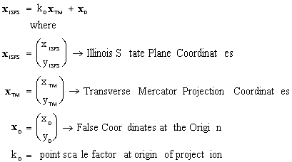
4.1.6 Transformation GCS : ISPS --------------------------18
4.1.6.1 Forward Transformation --------------------------19
4.1.6.2 Reverse Transformation --------------------------21
Appendix A --------------------------------------------------23
Appendix B --------------------------------------------------24
Appendix C --------------------------------------------------25
The Lattice Program is a C program designed to perform a transformation
of spatial and mapping plane coordinates between any two of the
coordinate systems which will necessarily be in use at the Fermi
National Accelerator Labortory (Fermilab). It is loosely defined
in concept upon a similar program written for use at the SSCL,
but the structure of the software is considerably different.
The software is currently implemented under the Windows 3.11 operating
system, and is compiled using the Microsoft Visual C++ compiler,
using the QuickWin compiler options for a 386 PC.
The program is designed to be run any number of times, with the
user defining the controlling parameters of the transformation
at each stage. It is possible to transform between any two of
the coordinate systems defined for use at Fermilab, and any number
of coordinates may be transformed. The coordinates are processed
in batches of 500. Testing of the software is by way of a baseline
set of coordinates provided by Fermilab, together with tests of
the internal precision of the program, and tests of transformations
using independent algorithms or known test data.
The data controlling any specific run of the software is input
interactively, in response to a number of prompts to the user.
The user is initially asked for the input device, which may be
the console or a data file, the coordinate system and the units
of the points in this system. The user is then prompted for the
same information regarding the output device, output coordinate
system, and output units. Finally a request is made for the number
of decimal places to which the data is to be output.
A full listing of the program is given in Appendix A, supplemented by flow charts in Appendix B. Annotated examples of the Input and Output files are given in Appendix C, and results of the software tests in Appendix D.
The program may be executed in the same way as any Windows 3.11
program. The user is presented with a window, in which the user
responses will appear, and in which the first of several prompts
to define the controlling parameters of the current transformation
is given.
The valid responses at each stage are indexed, and the user is
asked to input the appropriate index value. If the user inputs
an invalid value the user is once again prompted to input a different
response.
If data is to be input or output to a file, the program will prompt
for a filename. Any problems encountered opening the file will
result in the user being asked to enter a new filename, or choose
to terminate the program run. Naming restrictions of the Windows
3.11 operating system apply. Any data already in a specified output
file will be overwritten.
The formats for input data are given in Appendix C. The point
ID, and x, y, z (or their equivalent) should be input, with one
point given on a data line. Blank lines, and lines whose first
string is the US pound sign (#) will be ignored. Additional data
appended to the end of each data line will also be ignored.
If the input is to be through the console window, the data formats
will be supplied just before the user is asked to input the point
coordinate data. Rudimentary cut and paste is available. Each
paste is followed by a carriage return/linefeed, so if incomplete
lines are left after copying in data, the program will record
an error in the input data. Results output to this console may
be copied to the clipboard and pasted elsewhere.
The user is not presented with the input coordinate system in
the list of possible output coordinate systems.
If the input or output point data is indicated to be in a user
specified local geodetic coordinate system (LGS), the user is
prompted for the name and geodetic coordinates of the origin of
the system. The ellipsoidal height should be given in metres.
At the end of each requested transformation, the user is prompted to rerun the program for a new transformation, or to terminate the program. The user may stop the program executing by choosing Exit from the File Menu, which will close the Lattice window. The effects of doing this in the middle of a transformation are not defined.
There are nine coordinate systems which will be used by Fermilab,
some of which are merely intermediate steps in the transformation
between two other essential coordinate systems. A brief description
of each of these coordinate systems may be found in the FMI Document
[MI-0209].
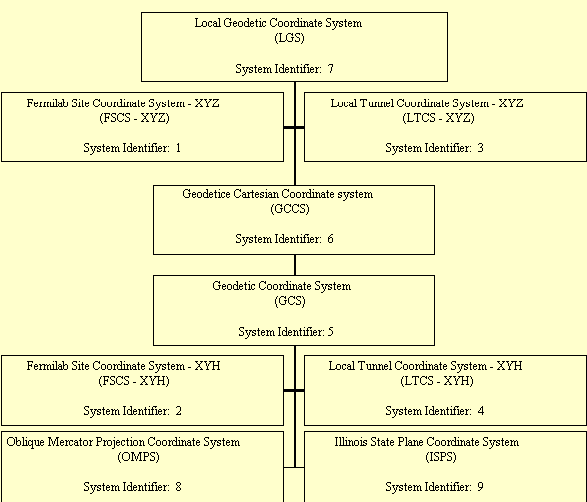
Figure 1.0 Coordinate Systems and Relationships between them
The transformation of coordinates from one of the coordinate systems
to another one, is a step wise process with a dictated route for
a given transformation. Each of the described coordinate systems
is directly related to at most two other systems, and this program
links the transformations between neighbouring coordinate systems
to provide the desired result.
The links between the various coordinate systems are shown in
Figure 1.0, with the coordinate systems identified by number,
corresponding to the listing provided by the program when it is
run.
All combinations of different start and finish coordinate systems are permitted by the program, but they must be different.
The relationship between FSCS -XYZ and FSCS -XYH is shown in diagramatic
form in Figure 2.0. It is noted that for the LTCS systems there
is an additional rotation applied about CMFI to bring the xy-plane
parallel to that defined in MI-0209.
The governing equations for each of the trasformation steps depicted
in Figure 1.0, are given below for both the forward and reverse
directions.
Reference: P., Vanicek, & E.J., Krakiwsky: Geodesy the Concepts,
1982. North- Holland Publishing Company.
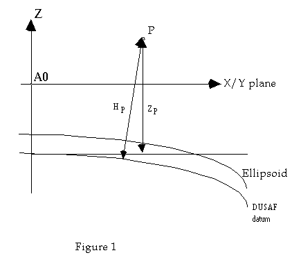
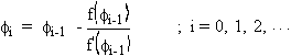
This transformation between the two Geodetic coordinate systems
may be explicitly expressed for the reverse transformation, but
the geodetic latitude and geodetic height are determined iteratively
for the forward transformation.
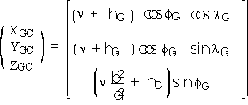
The equations describing the transformation from GCCS to GCS are:
Taking,
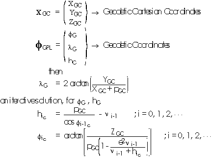
stopping criterion; suitable values for the precision of the transformation
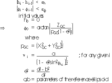
In the program,

The equations describing the transformation from GCS to GCCS are:
with notation as before.
Reference: P., Vanicek, & E.J., Krakiwsky: Geodesy the Concepts,
1982. North- Holland Publishing Company.
This transformation involves a change from a right handed system
(GCCS) to a left handed coordinate system (LGS), and therefore
also involves a reflection in the plane Y = 0. In addition there
is a rotation from the Geodetic coordinates of the User Specified
Origin, and a translation from this point.
The equations describing the transformation from GCCS to LGS are:
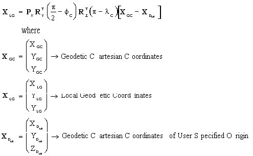
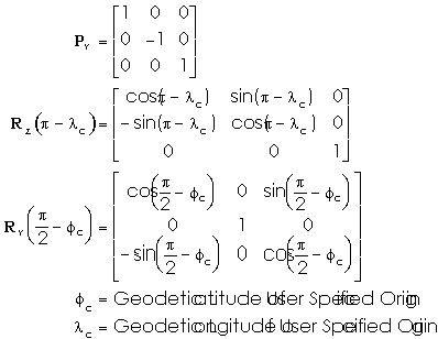
The equations describing the transformation from LGS to GCCS is:
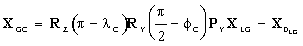
with notation as before.
The transformation between both the FSCS (XYZ) and LTCS (XYZ)
and the GCCS are essentially the same, with only the parameter
values of the transformation changing. The FSCS (XYZ) and the
LTCS (XYZ) are in reality modifications of two specific Local
Geodetic Systems, designed for Fermilab.
The LTCS system now also incorporates an additional rotation to
make the xy-plane of the final system parallel to the plane defined
in MI-0209.
The forward transformation involves a reflection in the X = Y
plane, to give a right handed system, followed by a rotation and
translation of the coordinates. This process is reversed to transform
the points the other way.
The equations describing the transformation from the GCCS to a
Fermilab (XYZ) Coordinate System, are initially those described
for the transformation from the GCCS to a LGS (see § 4.1.2)
with the origin at A0 (FSCS), or CFMI (LTCS). Following those
transformations:
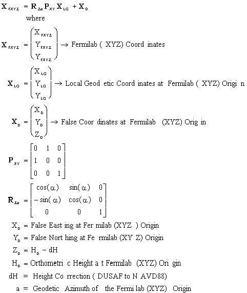
The equations describing the transformation from a Fermilab (XYZ)
Coordinate System to the GCCS are initially as follows:
This transformation is then followed by the transformation from
the LGS at the Fermilab (XYZ) origin, to the GCCS, (see §
4.1.2).
Notation is as before.
Reference: D.B., Thomson, M.P., Mepham, R.R., Steeves: The Stereographic
Double Projection, July 1977. Department of Surveying and Engineering,
University of New Brunswick, Fredericton, N.B., Canada. Technical
Report No. 46.
The transformation between both the FSCS (XYH) and LTCS (XYH)
and the GCS are essentially the same, with only the parameter
values of the transformation changing. The FSCS (XYH) and the
LTCS (XYH) are both Double Stereographic Mapping Planes, designed
for Fermilab.
The LTCS system now also incorporates an additional rotation to
the xy-coordinates to match the additional rotation incorporated
into the transformation from the GCCS to the LTCS -XYZ system
(see § 4.1.3).
The transformation between Geodetic coordinates and Double Stereographic
coordinates is a combination of two conformal transformations,
the first between ellipsoidal coordinates and spherical coordinates,
and the second between these spherical coordinates and the mapping
plane. The transformation from the sphere to the ellipsoid again
requires an iterative solution, performed here by the Newton-Raphson
Method.
The resulting coordinates are re-scaled by the scale factor, F0
(defined in MI-0209), to give true scale at
the origin of the Fermilab 720ft datum (Note that the point scale
factors at the origin of the two projections are both 1.0 for
the two Fermilab coordinate systems).
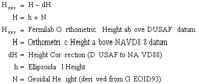
The determination of the orthometric height for each point uses
geoid height values estimated using the GEOID93 Model (see MI-0209).
These heights are then shifted to give the height above the DUSAF
datum.
The equations describing the transformation from GCS to DS are:
Transformation from the Ellipsoid to the Sphere
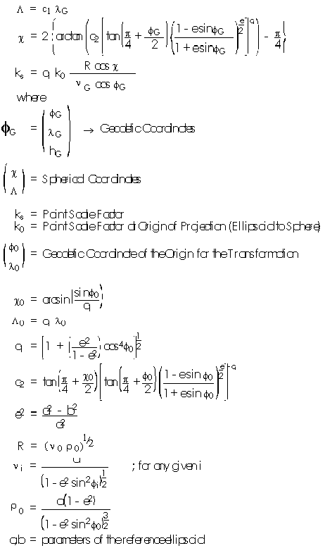
Transformation from the Sphere to the Mapping Plane
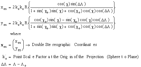
with unspecified notation as before.
Transformation into the Fermilab Double Stereographic Projection
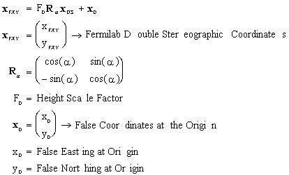
Orthometric Height in Fermilab Double Stereographic Mapping Plane
The equations governing the transformation from DS to GCS are
given below.
Transformation from the Fermilab Double Stereographic Projection
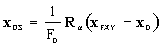
Transformation from the Mapping Plane to the Sphere
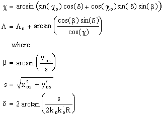
Transformation from the Sphere to the Ellipsoid

Newton-Raphson, iterative solution for 
in the program,

with notation as before.
Ellipsoidal Heights
Reference: J.P., Snyder: Map Projections -A Working Manual, 1987.
U.S. Geological Survey Professional Paper 1395, United States
Goverment Printing Office, Washington.
The transformation between the three dimensional Geodetic Coordinates
and the two dimensional Oblique Mercator Projection System in
use at Fermilab, as defined by a central point, and the azimuth
of the central line through the central point. A series is used
in the reverse transformation to avoid an iterative procedure
to determine the latitude.
The determination of the orthometric height for each point uses
geoid height values estimated using the GEOID93 Model (see MI-0209).
These heights are then shifted to give the height above the DUSAF
Datum (see § 4.1.3).
The equations describing the transformation from GCS to OMPS are:
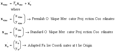

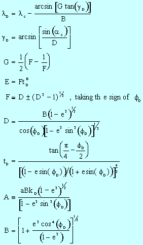
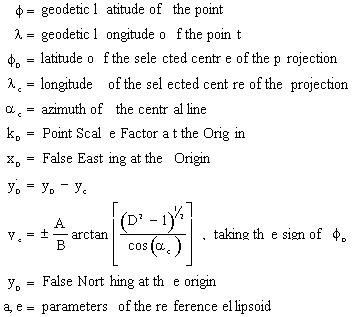
The equations describing the transformation from OMPS to GCS are:

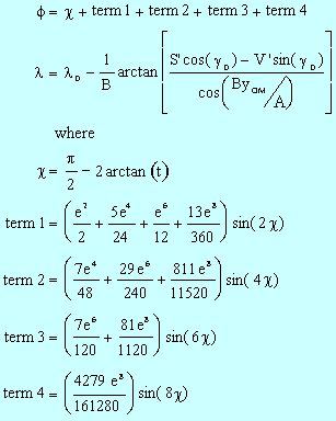
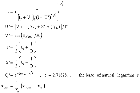
with unspecified notation as before.
Reference: J.P., Snyder: Map Projections -A Working Manual, 1987.
U.S. Geological Survey Professional Paper 1395, United States
Goverment Printing Office, Washington.
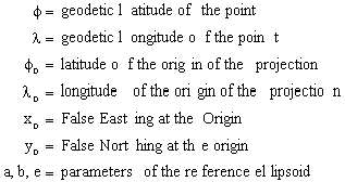
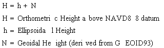
The transformation between the three dimensional Geodetic Coordinates
and the two dimensional ISPS mapping plane coordinates. The reverse
transformation uses an iterative procedure for the latitude.
The determination of the orthometric height for each point uses
geoid height values estimated using the GEOID93 Model (see MI-0209).
For this mapping plane these heights are not shifted to give the
height above the DUSAF, but are left as heights above the NAVD88
Datum.
The equations describing the transformation from GCS to ISPS are:

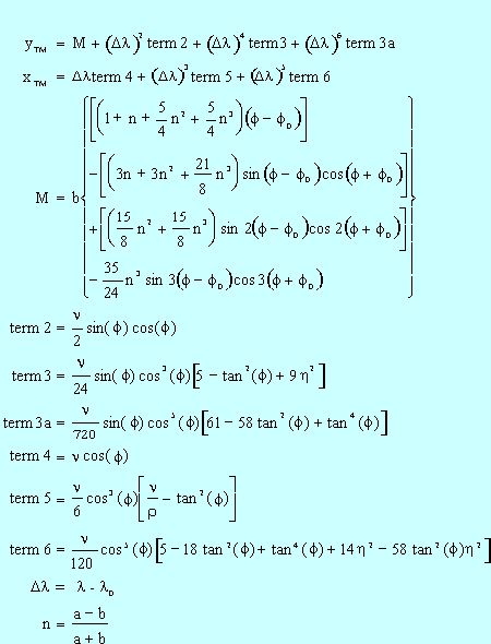
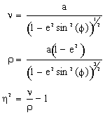
Orthometric Height in Illinois State Plane Coordinate System
The equations describing the transformation from ISPS to GCS are:
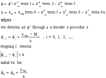
in the program,

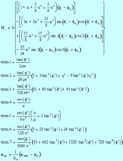
with unspecified notation as before.
Ellipsoidal Heights
