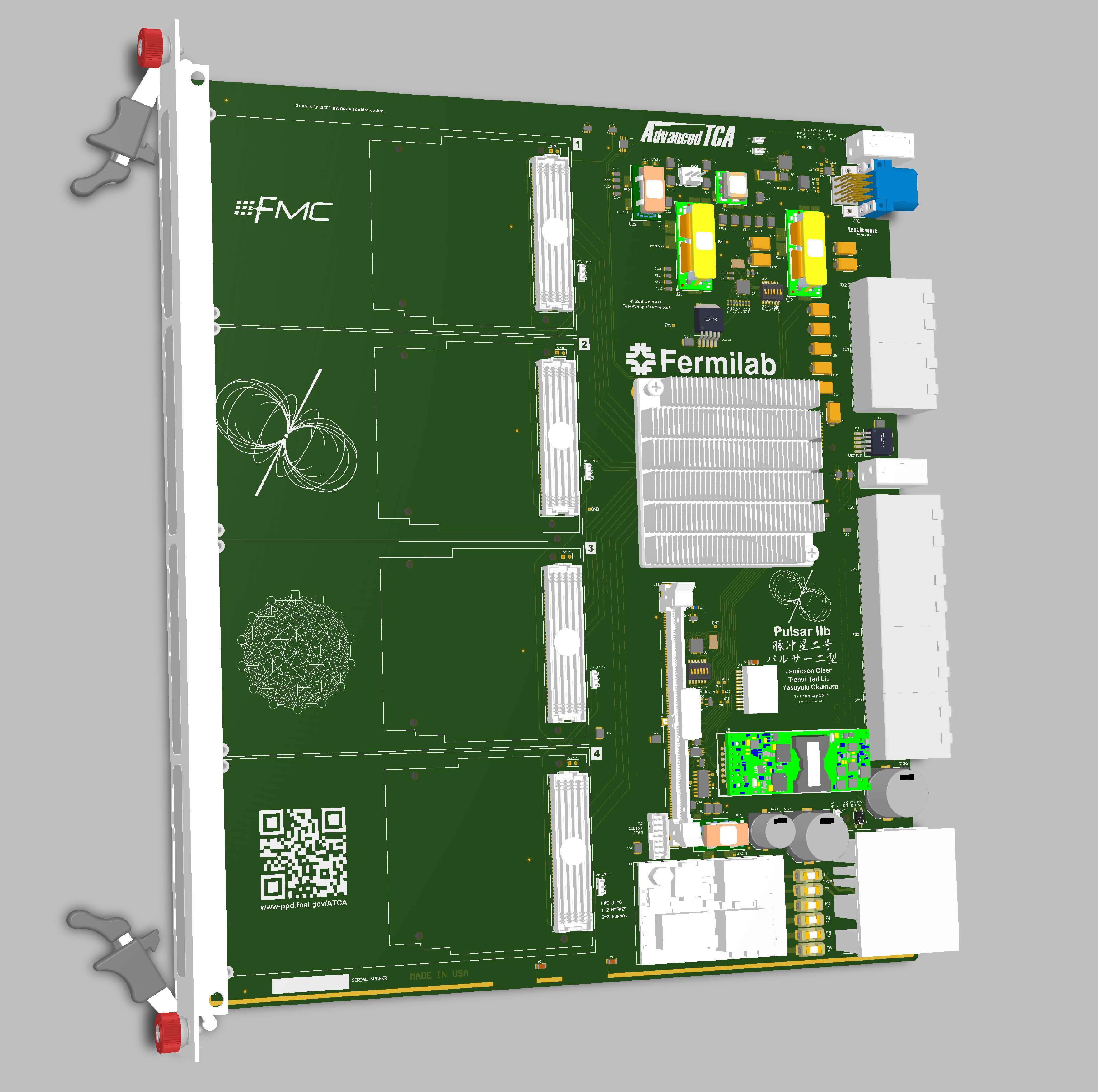
- Designed around a single Virtex-7 FPGA.
- Supported parts are: XC7VX415T, XC7VX485T, XC7VX550T or XC7VX690T
- 80 High speed SERDES transceivers (GTX/GTH)
- 40 for Rear Transition Module (up to 400Gb/s)
- 28 for the Full Mesh Fabric Interface (Ch 1 is 40Gb/s, Ch 2-13 are 20 Gb/s)
- 12 for the FMC cards (30Gb/s per FMC)
- Four FMC mezzanine cards, each has:
- 34 LVDS user-defined signals (LA00-LA34) + 2 LVDS output clocks
- 3 GTH/GTX bidirectional SERDES channels
- I2C bus
- 12V and 3.3V power, up to 35W total
- Compatible with the LAPP IPMC module
- 31 temperature, current, and voltage sensors.
- Board supports 10/100/1000-BASE-T Ethernet on Base Interface port 1
- 256MB DDR3 RAM.
- Shelf-wide clock distribution via the backplane Synchronization Interface.
- RTM is PICMG 3.8 compliant and supports hot swap.
Block Diagram, Video, and a high res picture of the board and RTM.
Compatible with our FMC Test Mezzanine.
Full mesh backplane link test results.
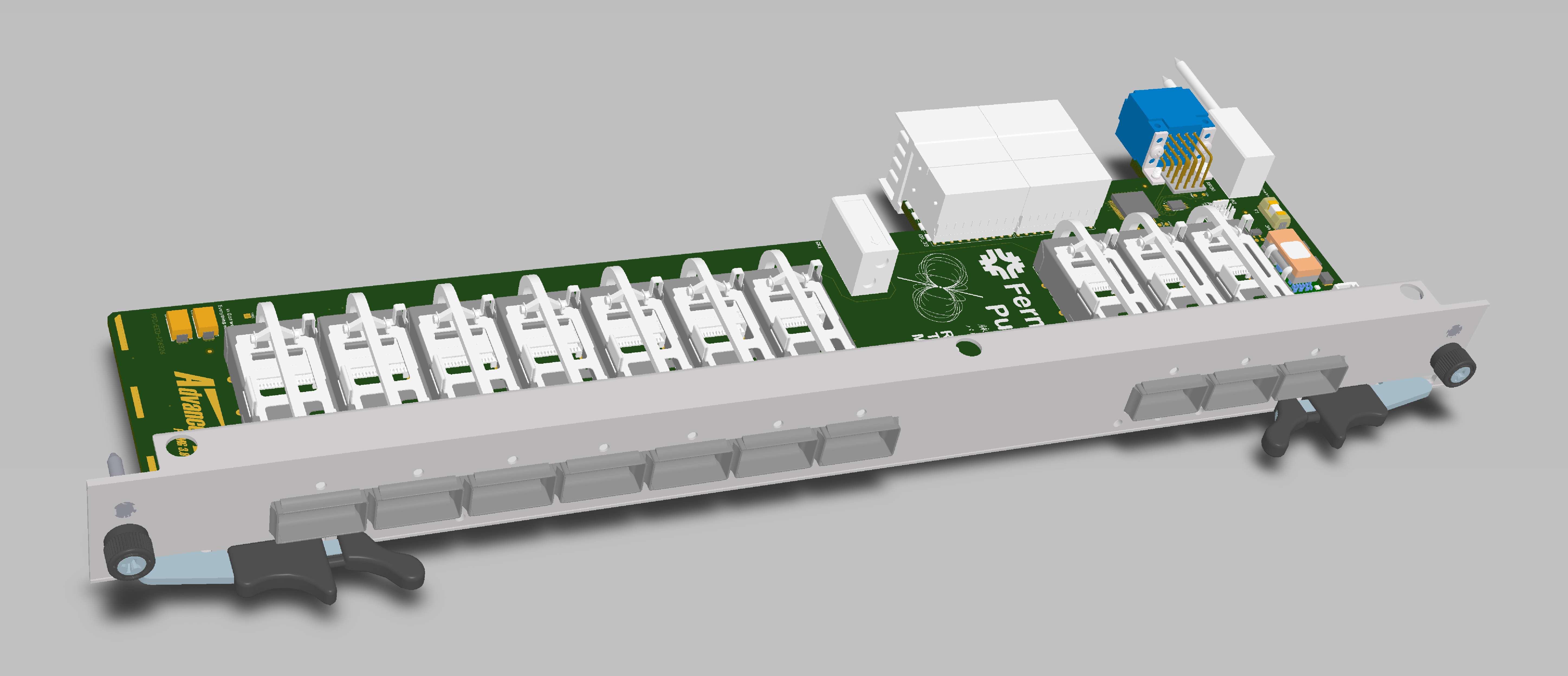
- Supports up to ten QSFP+ transceivers.
- Throughput up to 400 Gbps in each direction.
- ARM Cortex-M3 microcontroller for monitoring transceivers and IPMI communication
- PICMG 3.8 (Zone-3A) compliant, including hot swap.
- RGB status LEDs for maximum bling.
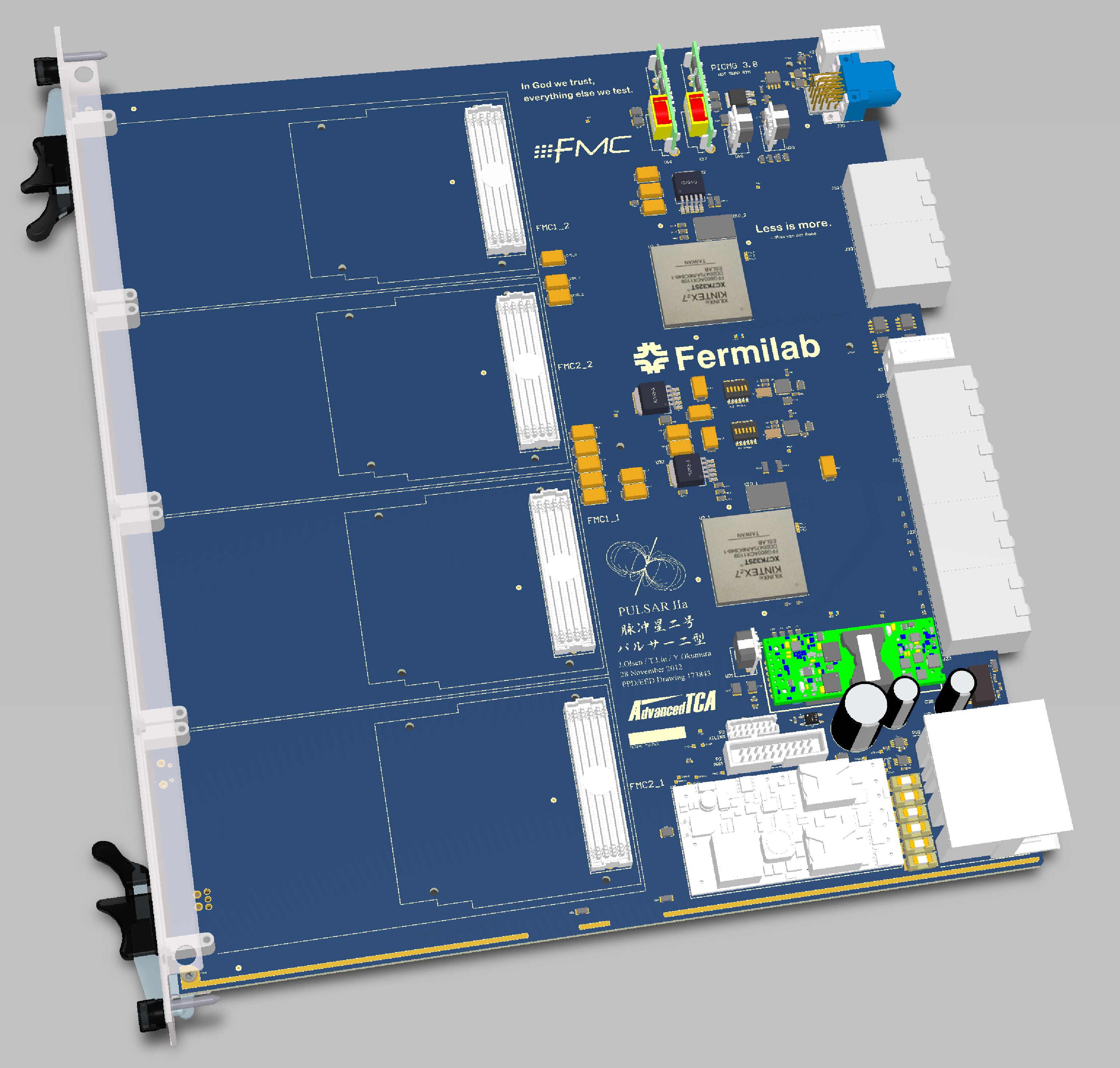
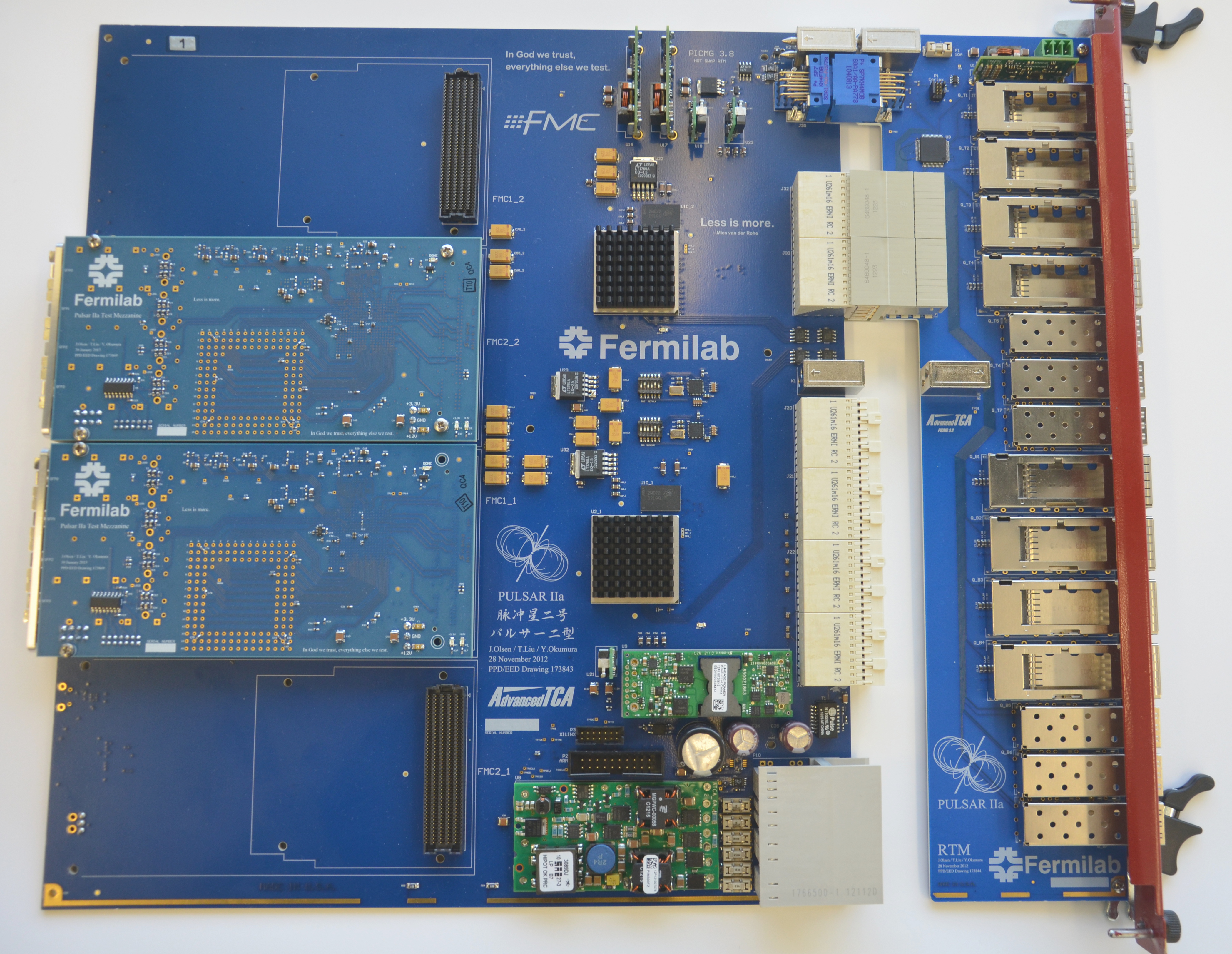
The Pulsar IIa prototype board is a general purpose processing engine based on a pair of Xilinx Kintex XC7K325T FPGAs. Each FPGA interfaces with two FMC mezzanine cards, DDR3 memory, the ATCA full mesh backplane (9 x 10Gbps), RTM (6 x 10Gbps) and a local interconnect bus (20Gbps). The Pulsar IIa is a successor to the Pulsar VME board widely used at CDF and MAGIC.
- Design Specification (for ATLAS FTK Data Formatter) [PDF]
- Block Diagram [PDF]
- Prototype board picture [JPG]
Compatible with our FMC Test Mezzanine.
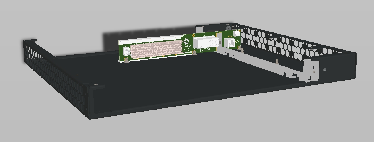
Mini Backplane 1U Chassis
The Mini Backplane is used to power a single
ATCA front board and RTM. This new layout is compatible with a
commercially available 1U chassis (contact us for details). This
chassis is powered from a 48VDC supply and includes up to 9 high
velocity fans and a fan controller board. On the Mini Backplane board
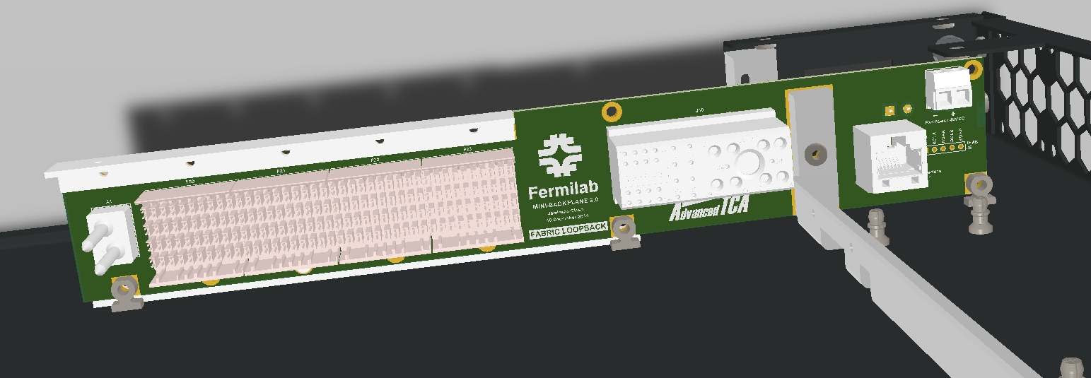
the IPMB signals are brought out to testpoints and the Base Interface (
10/100/1000 Ethernet) Channel 1 is brought out to an RJ45 connector.
All Fabric Channels are looped back to facilitate quick checkout of the
Pulsar II front board transceivers.
Detailed Front View,
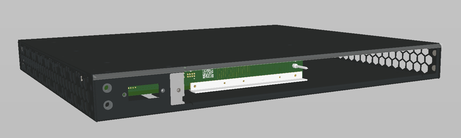
Chassis Rear View.